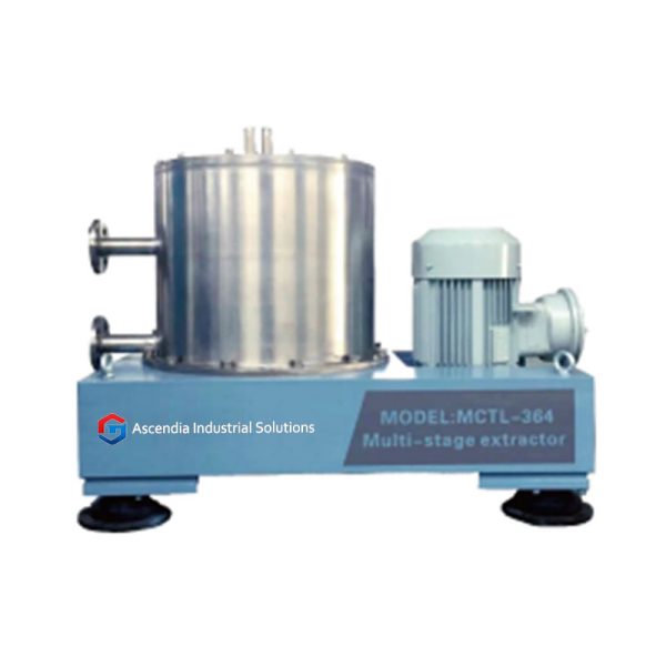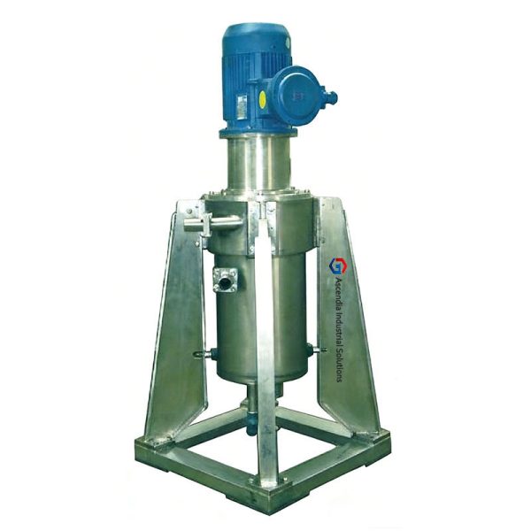
Blade Stirring Centrifugal Extractor
A top-suspended, low-shear centrifugal extractor designed for general industrial liquid-liquid separation and wastewater treatment.
- Phone:+86-17751233620
- E-mail:ascendiaauto@gmail.com
Key Features
|
Key Feature |
EN |
|
Key Feature 1 |
Upper Suspension Design: Eliminates bottom mechanical seals, preventing leakage and reducing maintenance. |
|
Key Feature 2 |
Low Shear Mixing: Optimized blade geometry prevents emulsification in sensitive feeds. |
|
Key Feature 3 |
Low Energy: Reduced motor power requirements compared to annular gap models. |
|
Key Feature 4 |
Corrosion Resistant: Available in polymer composites for acid/alkali resistance. |
|
Key Feature 5 |
Easy Access: Top-loading rotor allows for rapid maintenance. |
Process Characteristics (Technical Analysis):
Macroscopic Mixing Regime: Unlike the intense turbulence of annular contactors, the CTL uses a central blade to generate macroscopic circulation. This characteristic is critical for "Easy Separation" systems (large density difference $\Delta\rho > 0.1$) or feeds containing surfactants. It ensures phase equilibrium without generating secondary hazes (fine emulsions) that are difficult to separate, making it the ideal replacement for gravity settler tanks.
Typical Industries & Applications
|
1. Environmental Engineering: Oil-water separation (degreasing fluids), phenol removal from wastewater. |
|
2. Basic Chemical Manufacturing: Washing of non-viscous organic solvents (Acid/Alkali wash). |
|
3. Food Industry: Edible oil refining where gentle handling prevents oxidation. |
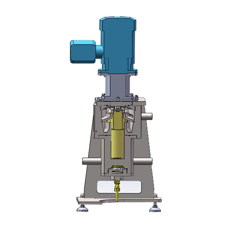
Working Principle
Step 1 (Mixing): Light and heavy phases enter the bottom mixing chamber. The rotating blade creates intense Taylor vortices for instant mass transfer.
Step 2 (Separation): The mixture is drawn into the high-speed drum. Centrifugal force (300-500G) rapidly stratifies the liquids.
Step 3 (Discharge): Liquids overflow via weirs into stationary collection volutes.
| Item |
Standard configuration |
Optional configuration |
|
Wetted parts material |
Stainless-steel wetted parts (drum and blade wheel) suitable for standard chemical service. |
High-alloy stainless steel (e.g. 316L, 904L) or titanium; abrasion-resistant coatings for solids-laden or highly corrosive systems. |
|
Mechanical layout |
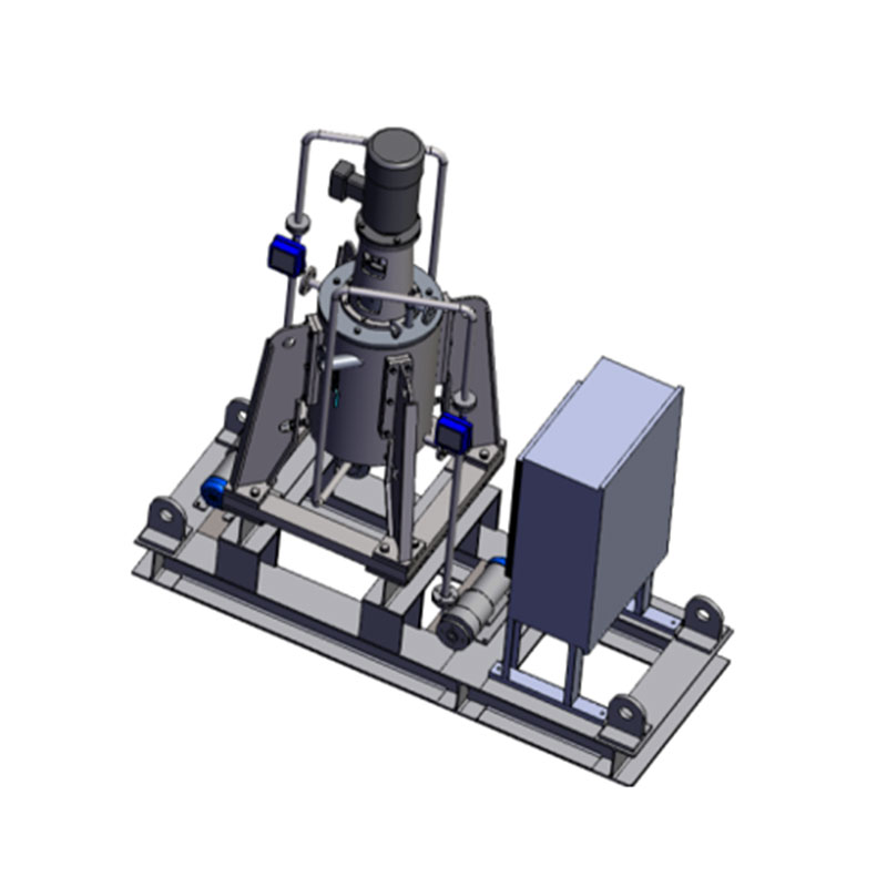
Top-hung rotor with upper bearing housing and simple support frame for easy access and maintenance. |
Enclosed frame with sound-attenuation panels, vibration-isolating base, integrated working platform and guardrails. |
|
Drive & control |
Direct-coupled motor, fixed-speed operation with local on/off control. |
Variable-frequency drive (VFD) for soft start and speed regulation; soft-starter; PLC control with interlocks to upstream / downstream equipment. |
|
Automation & safety |
Basic local instruments (ammeter, local start/stop) and mechanical overspeed protection. |
Bearing-temperature monitoring, continuous vibration monitoring, motor overload and earth-fault protection, nitrogen purging for solvent or explosion-risk service. |
|
Cleaning & washing |
Drain ports and access covers for manual cleaning of the drum and housing. |
CIP / spray-washing system for internal automatic cleaning, removable blade assemblies, quick-opening covers for fast inspection and turnaround between campaigns. |
Technical_Specs
| CTL Series - Blade Stirring Centrifugal Extractor (Standard) | Model | Rotor Diameter (mm) | Hydraulic Capacity (L/h) | Motor Power (kW) | Inlet/Outlet Size (mm) | Rotational Speed (rpm) | Separation Factor (G) | Net Weight (kg) | Dimensions (L×W×H) (mm) |
| CTL100-N | 100 | 10–200 | 0.3–0.6 | 15 | 3000 | 503 | 200 | 495×495×1200 | |
| CTL150-N | 150 | 100–800 | 0.4–0.8 | 25 | 2900 | 705 | 300 | 500×500×1200 | |
| CTL250-N | 250 | 800–2500 | 0.8–1.5 | 50 | 2000 | 555 | 750 | 725×725×1850 | |
| CTL350-N | 350 | 3000–6000 | 1.5–3.5 | 80 | 1500 | 440 | 1300 | 910×910×2150 | |
| CTL450-N | 450 | 6000–12000 | 4.0–7.0 | 80 | 1500 | 565 | 1500 | 1100×1100×2500 | |
| CTL550-N | 550 | 12000–25000 | 6.0–10.0 | 100 | 1000 | 307 | 2200 | 1300×1300×2820 | |
| CTL650-N | 650 | 25000–35000 | 10.0–13.0 | 125 | 1000 | 363 | 2600 | 1500×1500×2950 | |
| CTL800-N | 800 | 30000–50000 | 16.0–20.0 | 150 | 1000 | 447 | 4800 | 1800×1800×3100 | |
| CTL1000-N | 1000 | 40000–80000 | 18.0–22.0 | 150 | 800 | 357 | 6500 | 2100×2100×3800 |
Structure Diagram: