
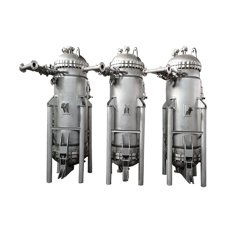
Cross-flow Membrane Filtration System
The Cross-flow Membrane Filtration System is designed for continuous solid–liquid separation and liquid clarification applications requiring stable filtration flux and reduced membrane fouling.
The system operates under tangential flow conditions, where feed liquid flows parallel to the membrane surface. This cross-flow mechanism generates shear force that minimizes cake buildup and extends membrane service life.
Available with ceramic or polymer membrane modules depending on application requirements.
- Whatsapp:+86 13812852189
- E-mail:sales@ascendiaindustrial.com
- E-mail:jacklau@ascendiaindustrial.com
Key Features:
Key Feature 1 — Stable Filtration Flux
Tangential flow reduces surface deposition and maintains consistent permeate flow over extended operating periods.
Key Feature 2 — Reduced Fouling & Longer Membrane Life
Continuous cross-flow shear limits particle accumulation and enhances operational stability.
Key Feature 3 — Modular System Design
Scalable membrane modules allow flexible capacity expansion.
Key Feature 4 — Suitable for Continuous Operation
Designed for steady-state industrial processing.
Key Feature 5 — Automated CIP Cleaning
Integrated cleaning-in-place system restores membrane permeability without disassembly.
Typical Design Range:
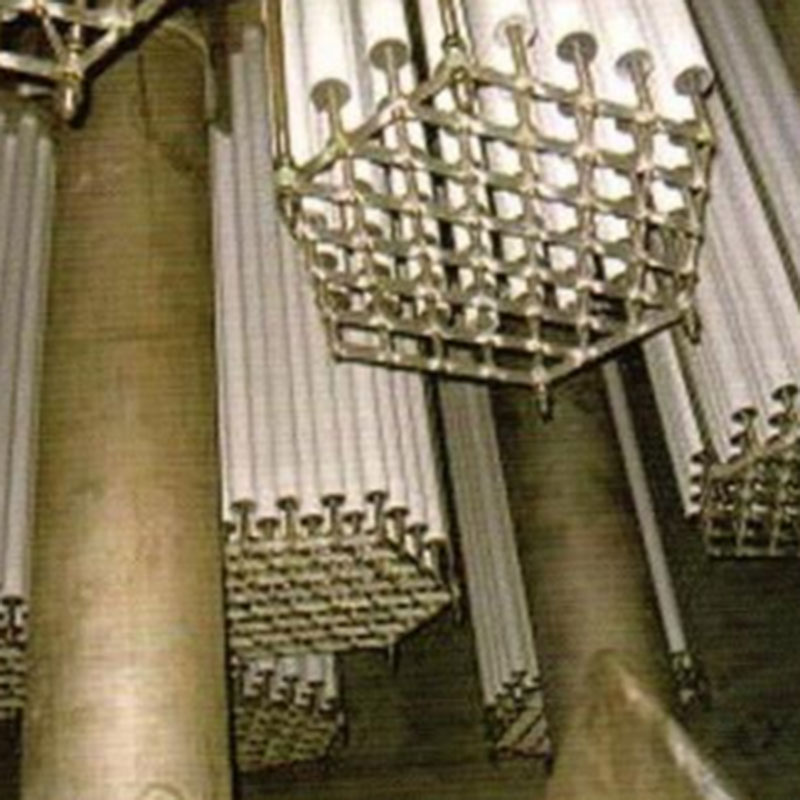
Membrane Type: Ceramic / Polymer (MF / UF optional)
Pore Size: 0.05 – 1.0 μm (depending on membrane selection)
Operating Pressure: 0.2 – 1.0 MPa
Operating Temperature: up to 150°C (ceramic)
Cleaning Method: CIP compatible
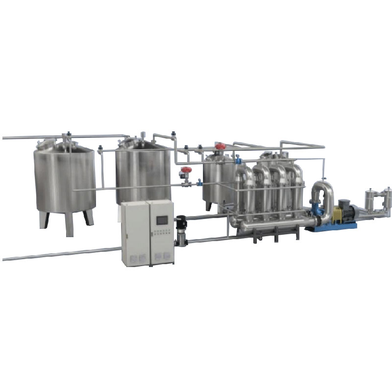
Configuration: Single module or multi-module skid
Typical industries and products:
• Catalyst recovery
• Fine chemical clarification
• Fermentation broth separation
• Wastewater reuse
• Beverage clarification
• Pharmaceutical intermediate purification
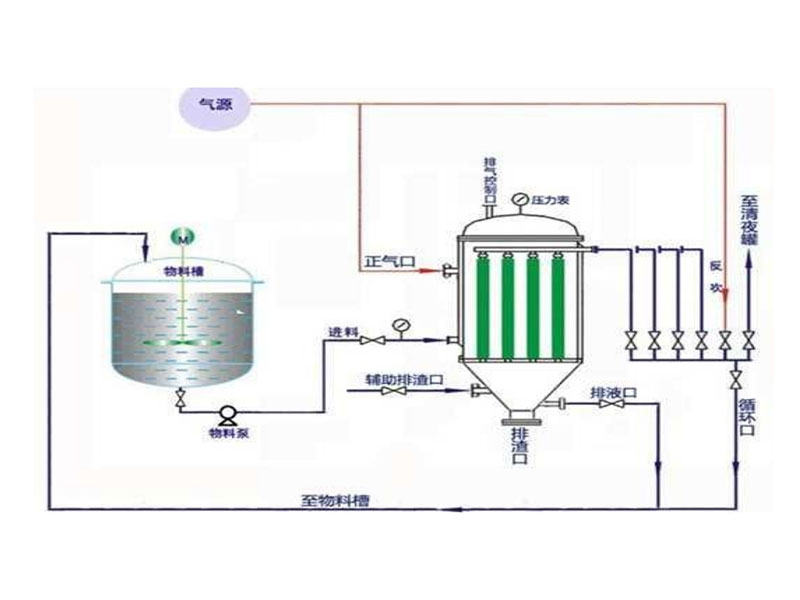
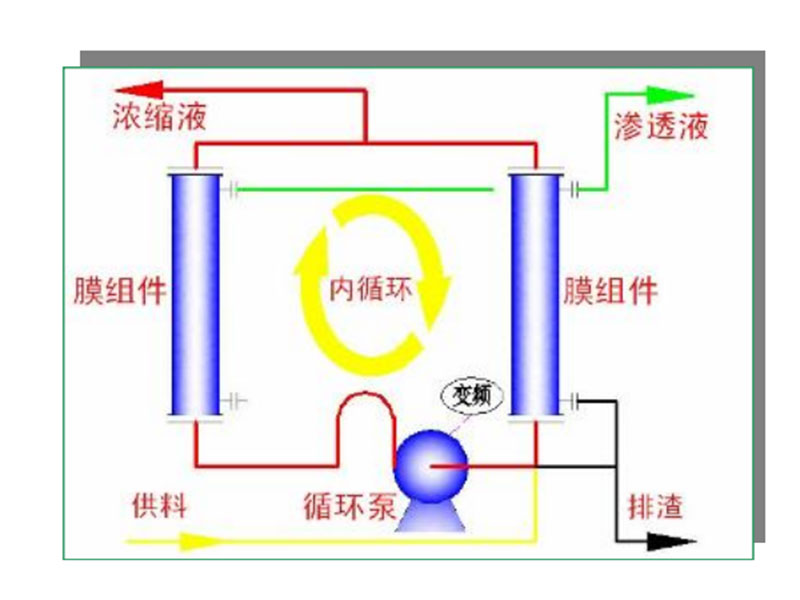
Working Principle:
The feed slurry is circulated through membrane modules at controlled pressure and cross-flow velocity.
Under transmembrane pressure (TMP):
Permeate passes through the membrane wall.
Retentate continues flowing tangentially, reducing particle deposition.
Key operating variables:
Transmembrane Pressure (TMP)
Cross-flow Velocity
Temperature
Membrane Pore Size
The balance of these parameters determines separation efficiency and flux rate.
Configuration Options:
| Product Name | Item | Standard Configuration | Optional Configuration |
| Cross-flow Membrane Filtration System | System Structure | Skid-mounted cross-flow membrane filtration unit with circulation pump and control panel | Full turnkey system including feed tank, buffer tank, and CIP tank |
| Membrane Module | Polymer membrane module (MF/UF) | Ceramic membrane module for high temperature and aggressive media | |
| Membrane Housing | Stainless steel 304 membrane housing | Stainless steel 316L or special alloy housing | |
| Pore Size Range | 0.1 – 1.0 μm (MF standard) | 0.05 μm or customized UF membrane grade | |
| Operating Pressure | 0.2 – 0.6 MPa design pressure | Up to 1.0 MPa reinforced design | |
| Operating Temperature | Up to 80°C (polymer membrane) | Up to 150°C (ceramic membrane) | |
| Circulation System | Centrifugal circulation pump with flow control valve | High-shear pump or VFD-controlled pump system | |
| Control System | Local control panel with pressure gauges and manual valves | PLC + HMI automatic control with data logging | |
| Instrumentation | Pressure gauges and flow indicators | Transmembrane pressure monitoring (TMP), temperature sensors | |
| Cleaning System | Manual cleaning ports, CIP-ready piping | Automatic CIP system with dedicated cleaning pump and tank | |
| Process Mode | Continuous cross-flow filtration mode | Multi-stage concentration and diafiltration mode | |
| Safety Features | Standard pressure relief valve | Explosion-proof motor and electrical components | |
| Automation Level | Semi-automatic operation | Full automatic with remote DCS/SCADA integration |
Technical_Specs:
| Product Name | Model | Drum diameter (mm) | Drum height (mm) | Max volume (L) | Max load (kg) | Max speed (rpm) | Max G-force | Motor power (kW) | Machine dimension L×W×H(mm) | Machine weight (kg) |
| PAUT Upper Suspension Scraper Bottom Discharge Centrifuge | PAUT 1250 | 1250 | 800 | 450 | 560 | 970 | 658 | 30 | 2100×2000×2600 | 5000 |
| PAUT 1320 | 1320 | 800 | 490 | 620 | 900 | 600 | 30 | 2100×2000×2600 | 5500 | |
| PAUT 1600 | 1600 | 1000 | 1000 | 1250 | 850 | 647 | 45 | 2700×2350×2900 | 10000 |
Structure Diagram:


